
0

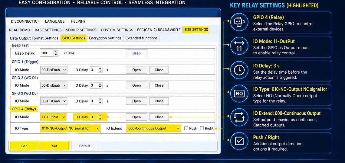
Configuration for MORX CR03, CR06, CR15 & CR20 RFID Readers
Follow the steps below to configure the relay output using the RFID Reader Demo software.
Step 1: Connect the RFID Reader
- Connect the MORX CR03, CR06, CR15, or CR20 reader to your PC.
- Open the RFID Reader Demo software.
- Select the correct COM port and click Connect.
Step 2: Open GPIO Settings
- Navigate to EISE SETTINGS.
- Click on the GPIO Settings tab.
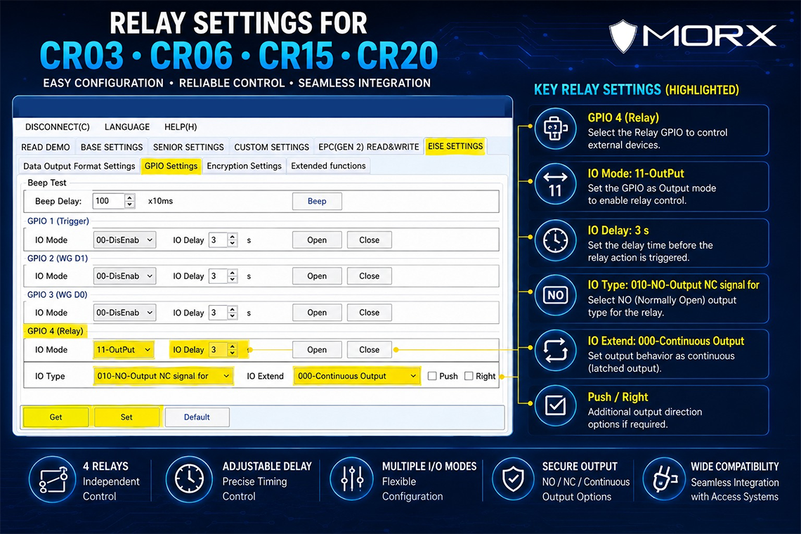
- Locate GPIO 4 (Relay), which is used for relay control.
Step 3: Set IO Mode
- Under GPIO 4 (Relay), find the IO Mode dropdown.
- Select 11-OutPut.
- This enables the relay output function.
Step 4: Configure Relay Delay
- Locate the IO Delay field.
- Enter the desired delay time (e.g., 3 seconds).
- The relay will activate after the specified delay.
Step 5: Select Output Type
- Under IO Type, choose:
- 010-NO-Output NC Signal For (Normally Open)
- Or another option based on your application requirements.
Step 6: Configure Output Behaviour
- In the IO Extend dropdown, select:
- 000-Continuous Output for a latched relay output.
- Or choose another mode for pulse-based operation.
Step 7: Configure Additional Options (Optional)
- Enable Push or Right options if required by your application.
- These settings provide additional relay control behaviour.
Step 8: Test Relay Operation
- Click Open to activate the relay.
- Click Close to deactivate the relay.
- Verify that the connected device responds correctly.
Step 9: Save Settings
- Click Set to save the configuration to the reader.
- Wait for the confirmation message.
- The relay settings are now stored in the reader.
Step 10: Verify Operation
- Present an RFID tag/card.
- Confirm that the relay activates according to the configured settings.
- Test multiple times to ensure reliable operation.
Example Configuration for Door Access Control
| Parameter | Value |
|---|---|
| GPIO | GPIO 4 (Relay) |
| IO Mode | 11-OutPut |
| IO Delay | 3 Seconds |
| IO Type | 010-NO-Output |
| IO Extend | 000-Continuous Output |
| Action | Open Door Relay |
This configuration allows the MORX RFID reader to trigger a door lock, gate controller, alarm, or other external device when a valid RFID tag is detected.
CategoryResources